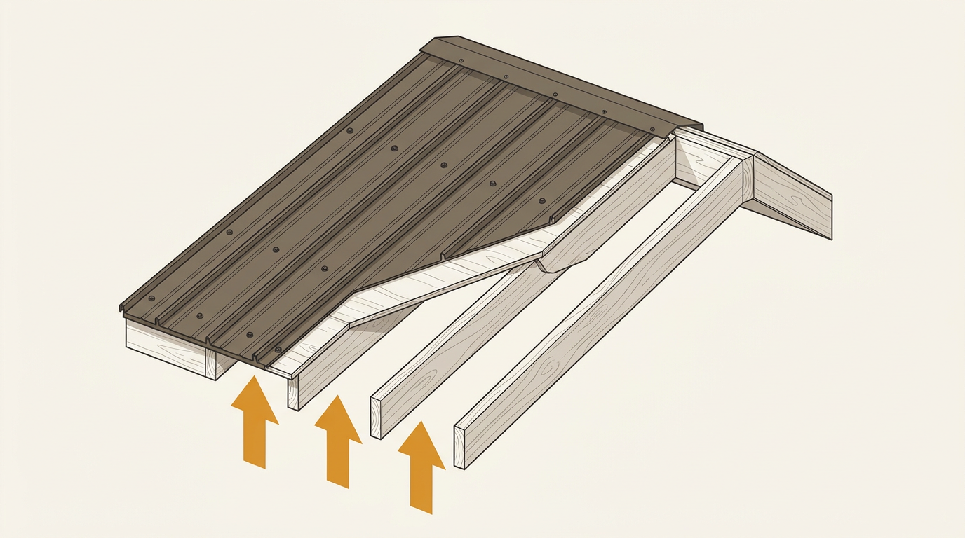
A design pressure is a number in pounds per square foot, and it belongs to one specific tested assembly: that profile, that gauge, that substrate, that clip, that clip spacing, that fastener. It is not a wind speed rating and it does not travel to a different assembly. "Our panel is rated for 180 mph" is not a claim a Florida Product Approval ever makes, because approvals are written in psf, and mph and psf are not interchangeable. This post covers where those numbers come from, what the test standards do, and how to read one off an approval without misusing it.
The Standards FBC 1504.3.2 Points At
The governing sentence is short. FBC-Building 1504.3.2 reads: "Metal panel roof system through fastened or standing seam shall be tested in accordance with UL 580 or ASTM E1592 or TAS 125." One section earlier, 1504.3.1 covers metal panel roof systems applied to a solid or closely fitted deck and points at FM 4474, UL 580 or UL 1897. Those are different documents doing different jobs, and the difference shows up in what you get back.
| Standard | What it does | What you get |
|---|---|---|
| UL 580, Tests for Uplift Resistance of Roof Assemblies | Tests a complete assembly, deck and deck attachment included, on a 10 ft by 10 ft specimen with positive pressure below and negative above | A pass or fail classification, not a design number |
| UL 1897, Uplift Tests for Roof Covering Systems | Continues on the same specimen, raising negative pressure in increments held one minute each until the assembly fails | A failure point and, more usefully, the failure mode |
| ASTM E1592, Structural Performance of Sheet Metal Roof and Siding Systems by Uniform Static Air Pressure Difference | Loads panels to failure at multiple spans. Its scope covers standing seam, trapezoidal, ribbed and corrugated panels from 0.012 to 0.050 inch thick | A family of design pressures across spans, not a single class |
| TAS 125-03, Standard Requirements for Metal Roofing Systems | The High Velocity Hurricane Zone metal roofing protocol, invoked by FBC 1523.6.5.2.4 alongside TAS 110 and the wind-driven rain testing of TAS 100 | The basis for an HVHZ metal roof approval |
Two notes. We are not publishing psf equivalents for the UL 580 class designations, because we could not verify them against a primary source and a wrong number here ends up in a submittal. And TAS 201, 202 and 203, the large missile impact and cyclic pressure protocols, are for envelope openings and cladding. If you see them cited on a metal roof panel, something is wrong with the document.
The 2:1 Margin of Safety
Test results are not design values. FBC 1504.9 says a margin of safety of 2:1 shall be applied to all wind-uplift resistance test results except where the test standard specifies one itself. FBC 1523.4 applies the same 2:1 margin inside the High Velocity Hurricane Zone. So a laboratory number and a number you may design to are separated by a factor of two before anyone opens a load table.
Which raises the question of what kind of number you are actually reading when you open one.
Allowable Load Versus Maximum Design Pressure
This is the distinction we are most careful about, and the one most likely to get flattened in someone else's marketing.
Standing seam design pressures in our catalog are allowable loads with a factor of safety of 2.0 already applied. The 5V figures are maximum design pressures. They are not the same kind of number. Never restate one as the other, and never set them side by side to decide which panel is stronger.
Standing seam, allowable loads with the 2.0 factor of safety already applied:
| Panel | Approval | Tested method | Allowable load |
|---|---|---|---|
| SL100, 1 inch snaplock, 24 ga | FL41812.05-R1 | Clips at 24 in. o.c. | 67.3 psf |
| SL100 | FL41812.05-R1 | Clips at 6 in. o.c. | 131 psf |
| SL150, 1.5 inch snaplock, 24 ga | FL41812.02-R1 | Clips at 24 in. o.c. | 86 psf |
| SL150 | FL41812.02-R1 | Clips at 12 in. o.c. | 108.5 psf |
| SL150 | FL41812.02-R1 | Clips at 6 in. o.c. | 116 psf |
| NS100, 1 inch nailstrip, 24 ga | FL41812.04-R1 | One #10 in the panel slot at 16 in. o.c. | 59.75 psf |
| NS100, 24 ga | FL41812.04-R1 | Slot fastener at 6.75 in. o.c. plus two eclipse-head fasteners in the pan at 12 in. o.c. | 153.5 psf |
| NS100, 26 ga | FL46540.01-R0 | One #10 in the panel slot at roughly 5-3/16 in. o.c. | 56 psf |
| M150, 1.5 inch mechanical lock, 24 ga steel | FL46540.02-R0 | Clips at 8 in. o.c., seamed to 90 degrees, sealant on the male leg | 131 psf |
5V Crimp, maximum design pressures:
| Material | Approval | Fastener pattern | Maximum design pressure |
|---|---|---|---|
| 0.032 in. aluminum over 1/2 in. plywood | FL24397.1 | 12 in. o.c. across the panel, 14 in. o.c. along it | -71 psf |
| 26 ga steel over 7/16 in. OSB | FL24397.2 | 12 in. o.c. across the panel, 16 in. o.c. along it | -52.5 psf |
| 26 ga steel, enhanced pattern | FL24397.3 | Two fasteners at 12 in. o.c. across, 24 in. o.c. along | -63.5 psf |
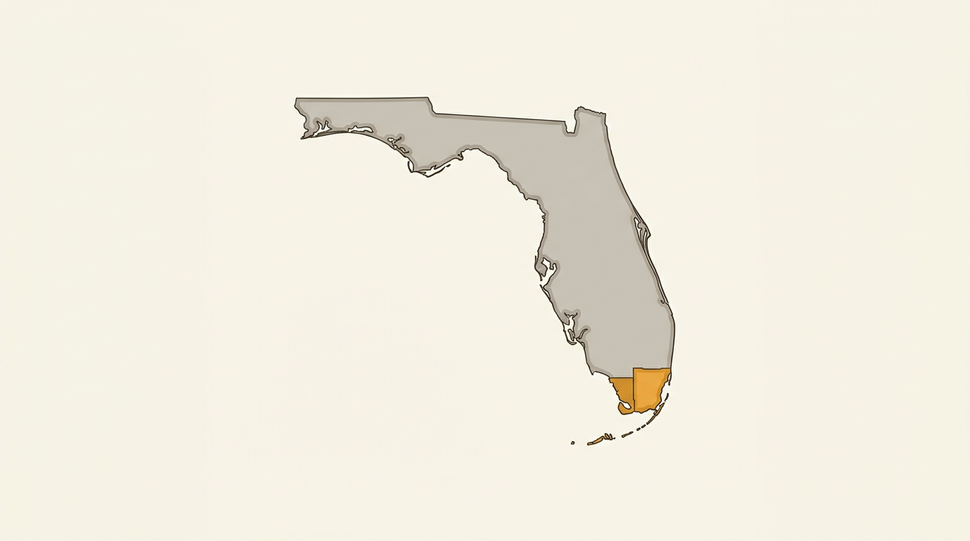
Every figure above was read off the signed approval for that panel. Approvals get revised, so verify the current revision at floridabuilding.org before you submit anything. Note also that NS100 and 5V are approved for use outside the HVHZ only, while SL100, SL150 and M150 hold HVHZ and Miami-Dade approval. A load number is worthless in Broward or Miami-Dade if the panel is not approved there in the first place.
Why There Is No Formula From Design Pressure to Fastener Spacing
Contractors ask for a conversion. There is not one, and anyone who gives you one is guessing.
Look at SL150 in the table. Same panel, same 18 ga clip, same two #12 fasteners per clip, same 15/32 inch plywood. Moving the clips from 24 inches on center to 12 inches does not double the allowable load, and moving from 12 to 6 inches adds less again. The relationship is not linear, it is not proportional to fastener count, and it is different for every profile.
Span works the same way. ASTM E1592 is run at multiple spans precisely because a panel's behavior changes with them, which is why it yields a family of design pressures rather than one class. What you get to use is the specific tested configuration in the approval's load table. Change the clip, the fastener, the substrate or the spacing to something untested and you no longer have a rating, you have an opinion.
So the workflow runs one way: calculate the required design pressure for the site and roof zone, find a tested method that meets or exceeds it, and build that method.
Nine Things To Check on an Approval Document
- The code edition it was evaluated against. An approval evaluated against a superseded edition is the first thing a good plans examiner looks for.
- The HVHZ flags. Every listing carries an approved-in-HVHZ yes or no and an approved-outside-HVHZ yes or no. Read both.
- The exact tested assembly: substrate and alloy, coating, panel width, seam type, minimum slope.
- Deck type and deck attachment. Real approvals state that the deck is a separate design problem outside the scope of the evaluation. The deck is your responsibility, not the panel manufacturer's.
- The design wind load appendix. This is the load table you will actually build to.
- Whether fire classification is covered. Often it explicitly is not, which matters because metal over a plywood or OSB deck is not automatically Class A under FBC 1505.
- Whether it is signed and sealed by a Florida professional engineer, with registration and organization numbers shown.
- The quality assurance agency.
- The precedence clause. Most read like this: where discrepancies exist between these sources, the more restrictive and FBC compliant installation detail shall prevail.
Getting the Site Wind Load Right
The load side of the equation goes wrong more often than the resistance side, usually for one of two reasons.
The Florida Building Code, 8th Edition (2023), references ASCE 7-22, not ASCE 7-16. It took effect December 31, 2023. This is the most common factual error in Florida roofing content. ASCE 7-22 generally lowered roof pressures for slopes over 7 degrees and simplified the zone layout, taking gable roofs from five zones to three and hip roofs from four to three. Low-slope coefficients from 0 to 7 degrees are unchanged.
The ATC Hazard By Location tool cannot be used for Florida. The Commission's own fact sheet says it cannot be used to obtain site-specific wind speeds as of December 31, 2023. Use the ASCE 7 Hazard Tool at ascehazardtool.org, or the local building department. Peninsula wind speeds did not change under ASCE 7-22; the western panhandle went up for Risk Categories I, II and III.
One more caution: do not take a wind speed off a blog table, which is why there is not one here. The code says the exact location of wind speed lines is established by local ordinance using recognized physical landmarks. Risk Category II is the default for nearly all houses and ordinary commercial buildings, and Figure 1609.3(1) is its map, but the site-specific number comes from the tool or the AHJ.
How This Lands on a Real Job
The chain is short and every link is checkable. Site wind speed and exposure produce a design pressure by roof zone. The zone pressure is compared against a tested method in the approval for the exact panel, gauge and substrate you are installing. That method dictates clip or fastener spacing, and that spacing is what the crew builds and what the inspector verifies.
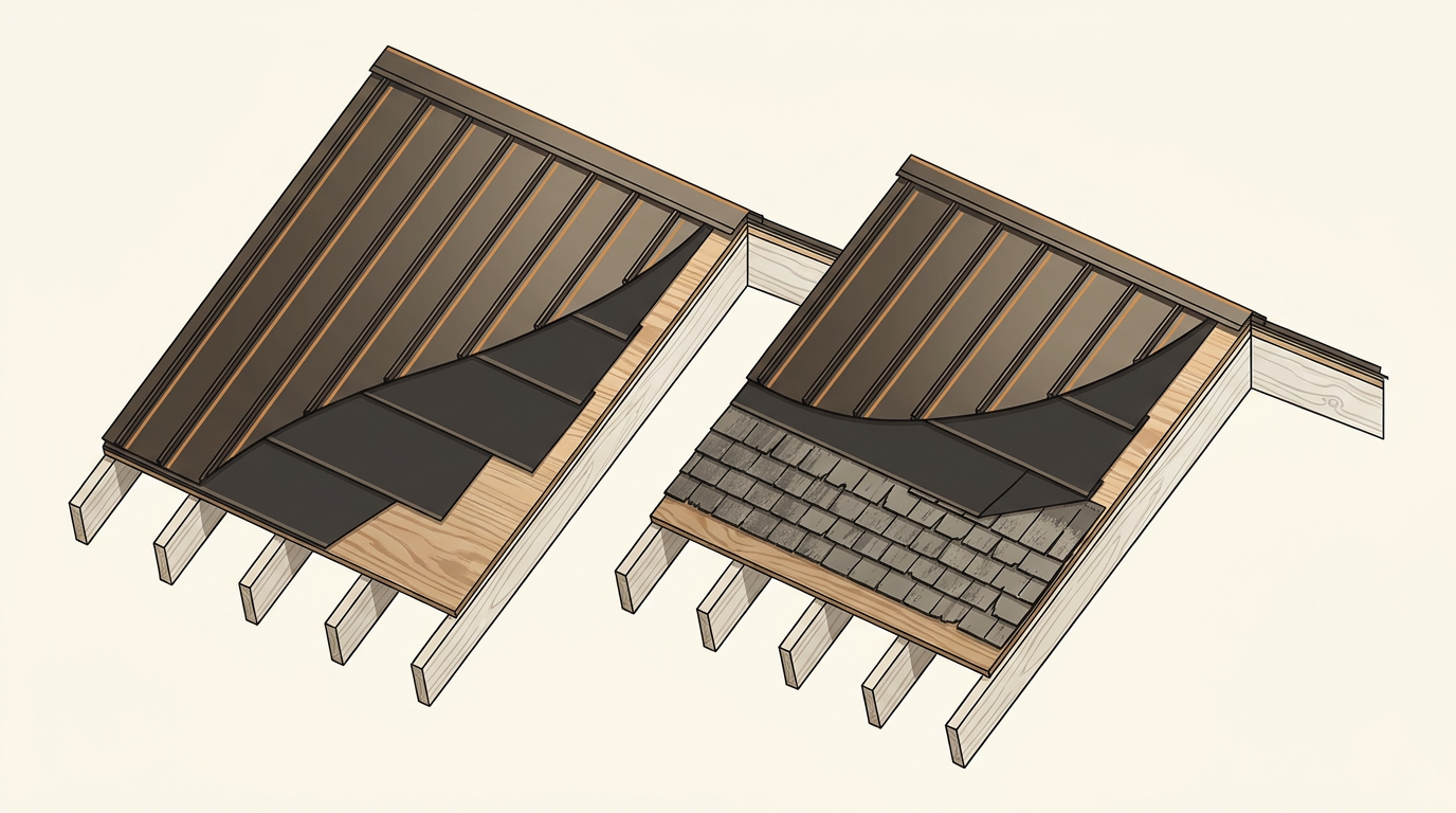
Our standing seam profiles and 5V crimp each carry their own approval, and the approval and installation documents are on the site so you can pull the load table before you write the proposal. On a re-roof, read our post on what the code allows over existing shingles first, because the deck decision changes which tested assembly you may use. Then the permit post covers what travels with the application, and Instant Metal Quote prices panel and trim once the profile is set. For a second set of eyes on a load table before submittal, call sales.